Diabetes Learning Content Design
Overview
The following diagram shows the content pipeline used with the target being an Adobe Aero prototype that provides AR medical tutorials. This content is part of the AR Health Project.
Publicly available tools were used to produce content in industry standard format within an intuitive workflow. The main tools used are:
- Adobe Figma was used for the user interface design of icons, labels and buttons.
- Adobe Sampler, Maya, and Blender are used for geometry, materials, and animations.
- ChatGPT was used for text generation and ESpeak for converting text to audio instruction.
Scripting to generate corresponding text and audio instruction is being investigated.
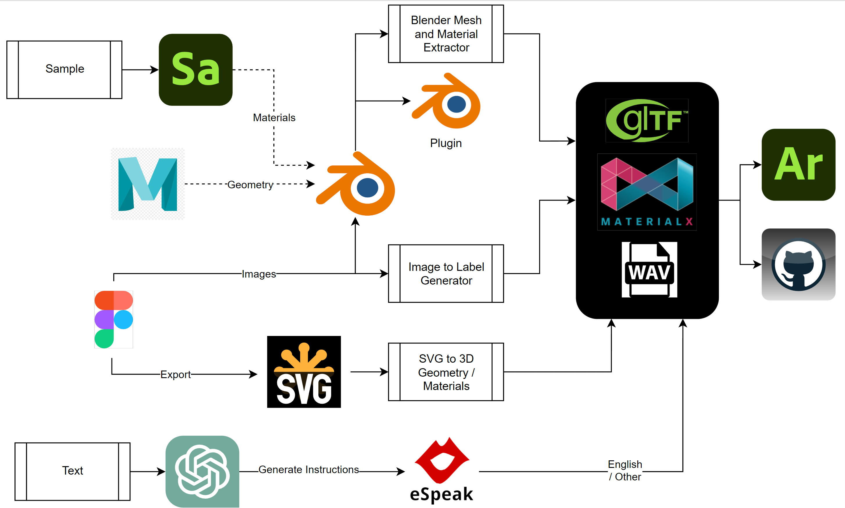
Figure 1 : This diagram shows the overall creation and process of the various types of data used for the prototype.
Modelling The Lancing Device and Meter
Photographs of a physical diabetes lancet and meter were taken and used as reference images to construct parametric models within Maya. These models were then exported to Blender for conversion to meshes, material association and creation of animations.
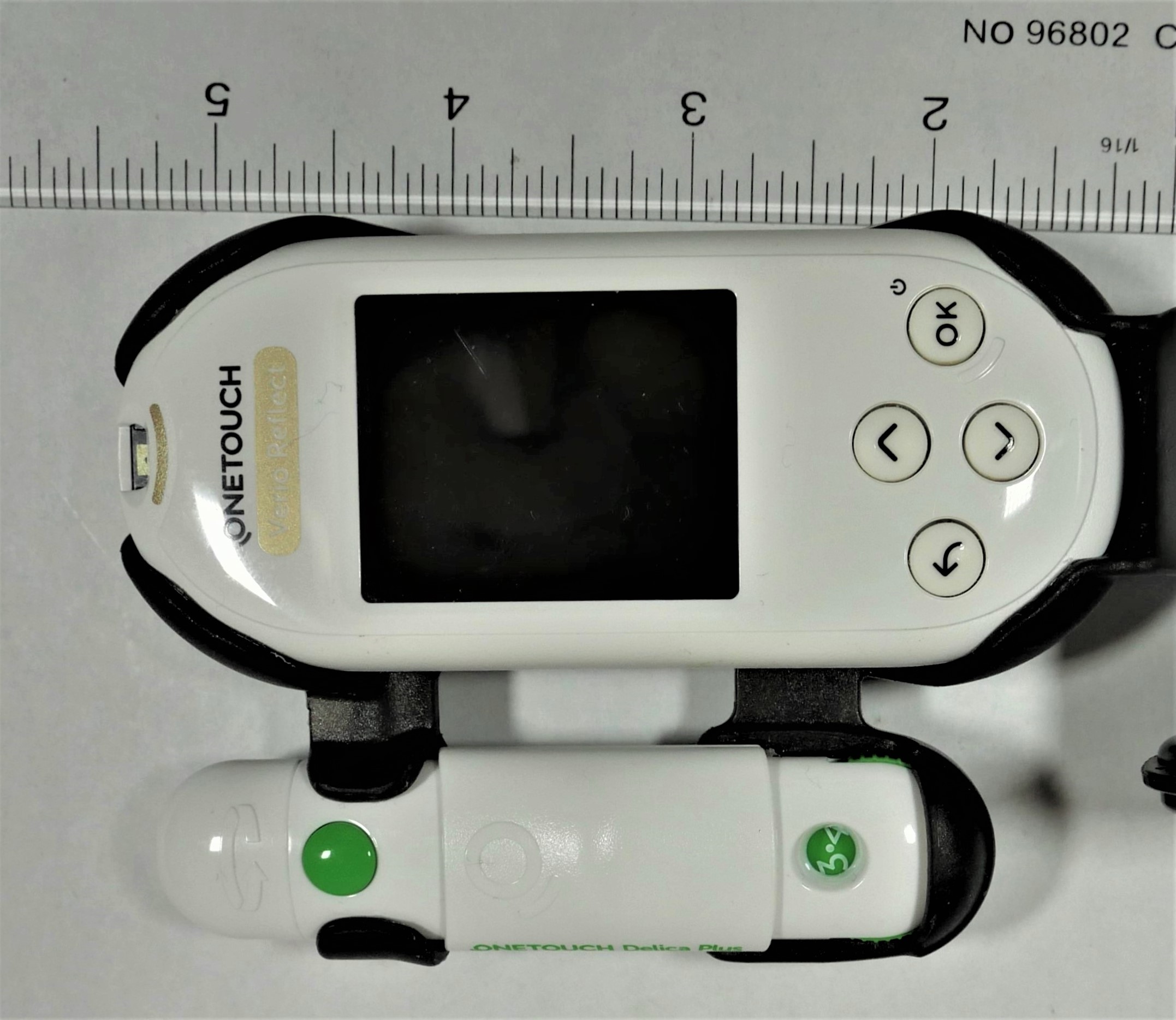
Figure 2: Sample reference photographs
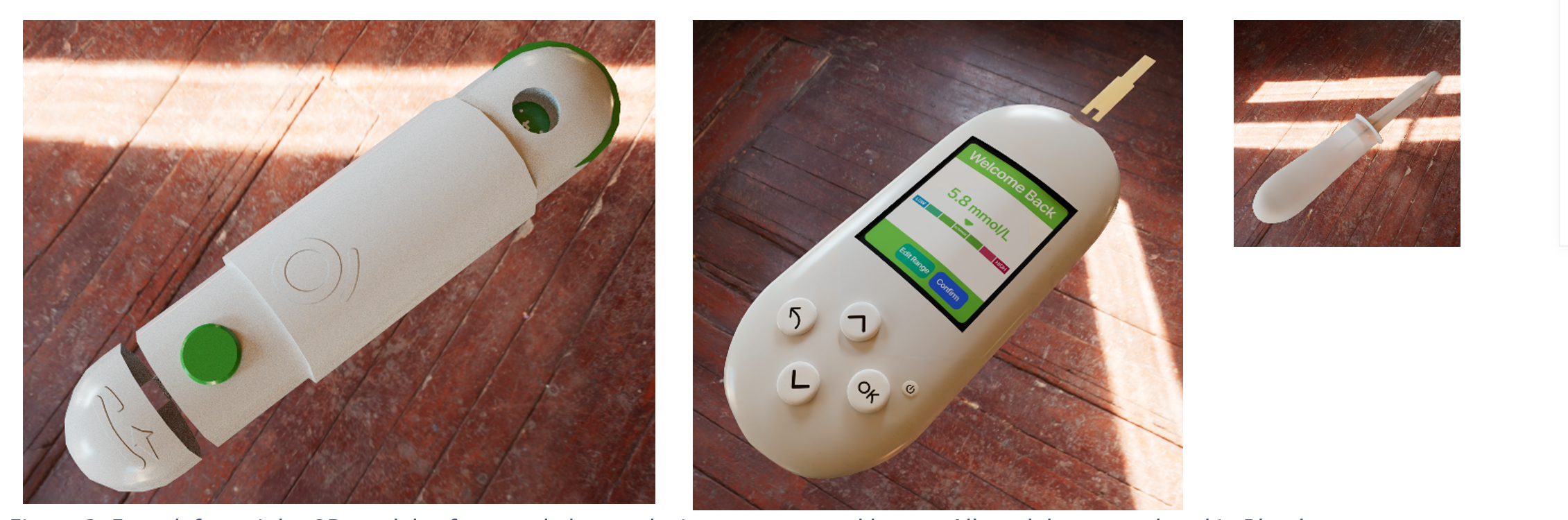
Figure 3: From left-to-right, 3D models of a lancing device, a meter, and a lancet. All models are rendered in Blender.
Material parameters were made to be as accurate as possible to the actual material using a physical lancing device/meter as well as company device specifications. Scanning of materials using Adobe Sampler was attempted as well as entering values from a property database. Bump maps were not used from Sampler but instead were created based on 2D vector graphics.Matching the 3D model dimensions with the real-world dimensions was performed within Blender and again in Aero as dimension (transformation) information is lost on import to Aero.
Blender Material Animation and Mesh Plugin and Script
The 3.5 Blender release includes the MaterialX Python package allowing for the ability to easily write Python scripts for material extraction. This is incorporated into a stand-along script as well as a Blender add-on allowing for automated extraction of geometry (meshes), animation, and materials.All meshes are separated into individual files and imported as model and user interface parts. Separation is required as Aero does not preserve the scene hierarchy nor separation of parts on import. Separation is required to allow individual placement and association of actions and triggers per part.
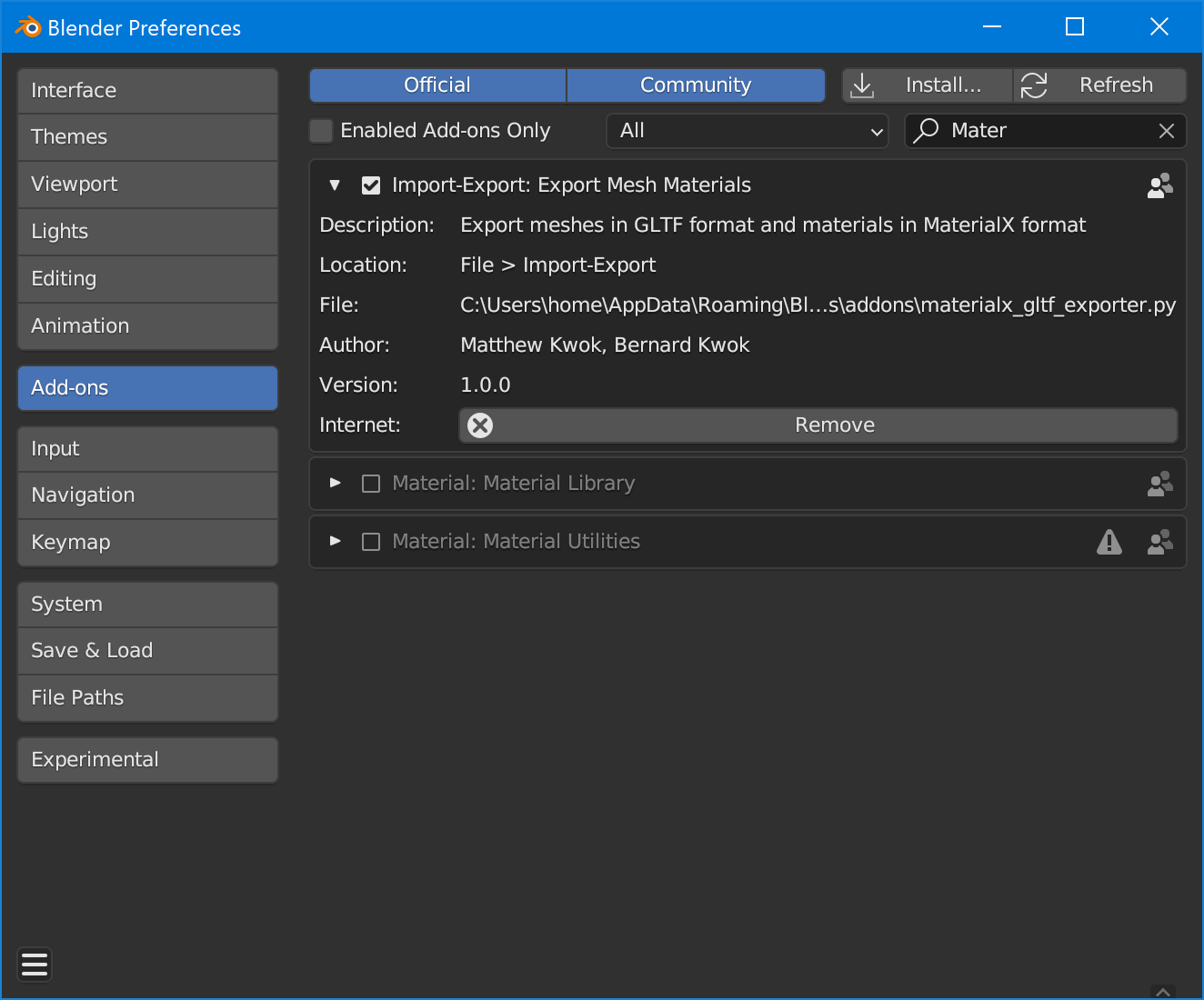
Plug-in Installation
- First go to the edit section in the top tab menu then navigate to the preferences sub menu.
- Select the add-ons tab within the preferences menu.
- Click the install tab on the upper right to add the plugin locally.
- Browse to material_gltf_exporter.zip and click the install add on button located on the upper right of the window.
- In the add-ons section click the checkbox next to the plug-in name to enable the add-on
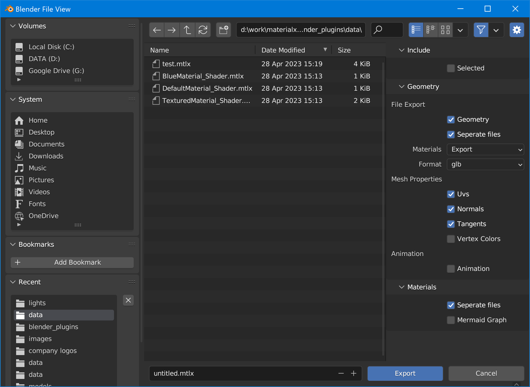
Plug-in Usage
- Use the selection tool and drag over the objects that you want to export to export “Selected” objects.
- Go to the file section in the top menu then go to the Export submenu then go to MaterialX/GlTF to open the export window.
- Choose from various file, mesh, and material options before exporting. Note that by default exporting of each mesh to separate files is enabled.
- Choose a folder to export to.
- Test if the GLTF file retains exported assets by opening it in a model viewer.
- Test materials and meshes in a model viewer to see if the export worked.
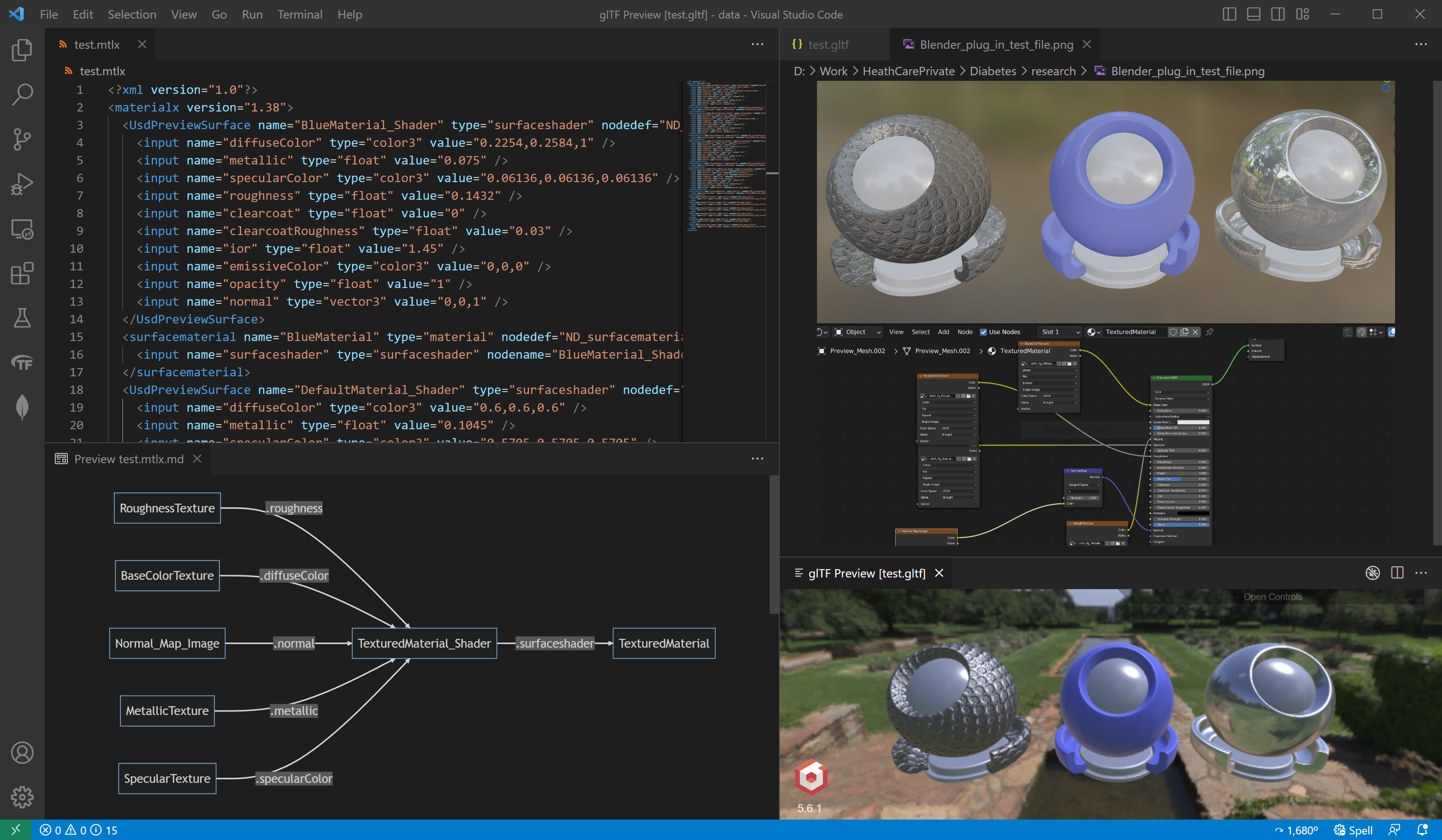
Figure 4: Examining the results of a test export. MaterialX output is shown in the left panel, the Blender scene in the in the upper right panel, shader diagram output in the lower left panel, and the GLTF preview in the lower right panel.
For efficiency, the command line script version of this is used taking the diabetes Blender files as input to produce all the content required to send to Aero. The command line arguments are as follows:
usage: blender_mtlx.py [-h] [--writeGeom WRITEGEOM] [--writeGeomMaterials WRITEGEOMMATERIALS]
                       [--separateGeomFile SEPARATEGEOMFILE] [--separateMtlxFile SEPARATEMTLXFILE]
                       [--writeMtlxGraph WRITEMTLXGRAPH] [--outputPath OUTPUTPATH]
                       inputFileName

Extract MaterialX materials from a Blender file. Optionally export meshes as GLTF files
positional arguments:
  inputFileName         Root name of image files to examine.

options:
  -h, --help            show this help message and exit
  --writeGeom WRITEGEOM
                        Set to True to export meshes in GLTF format. Default is False.
  --writeGeomMaterials WRITEGEOMMATERIALS
                        Set to True to write materials as part of mesh export. Default is False.
  --separateGeomFile SEPARATEGEOMFILE
                        Set to True to write meshes to separate GLTF files. Default is False.
  --separateMtlxFile SEPARATEMTLXFILE
                        Set to True to write each material to a separate MaterialX file. Default is False.
  --writeMtlxGraph WRITEMTLXGRAPH
                        Set to True to export Mermaid graph for materials. Default is False.
  --outputPath OUTPUTPATH
                        File path to output shaders to. If not specified, is the location of the input document is
                        used.
Below is a snapshot of some of the content stored as Blender files, and a snapshot of the resulting folder of content which can directly be imported into Aero.
 |
 |
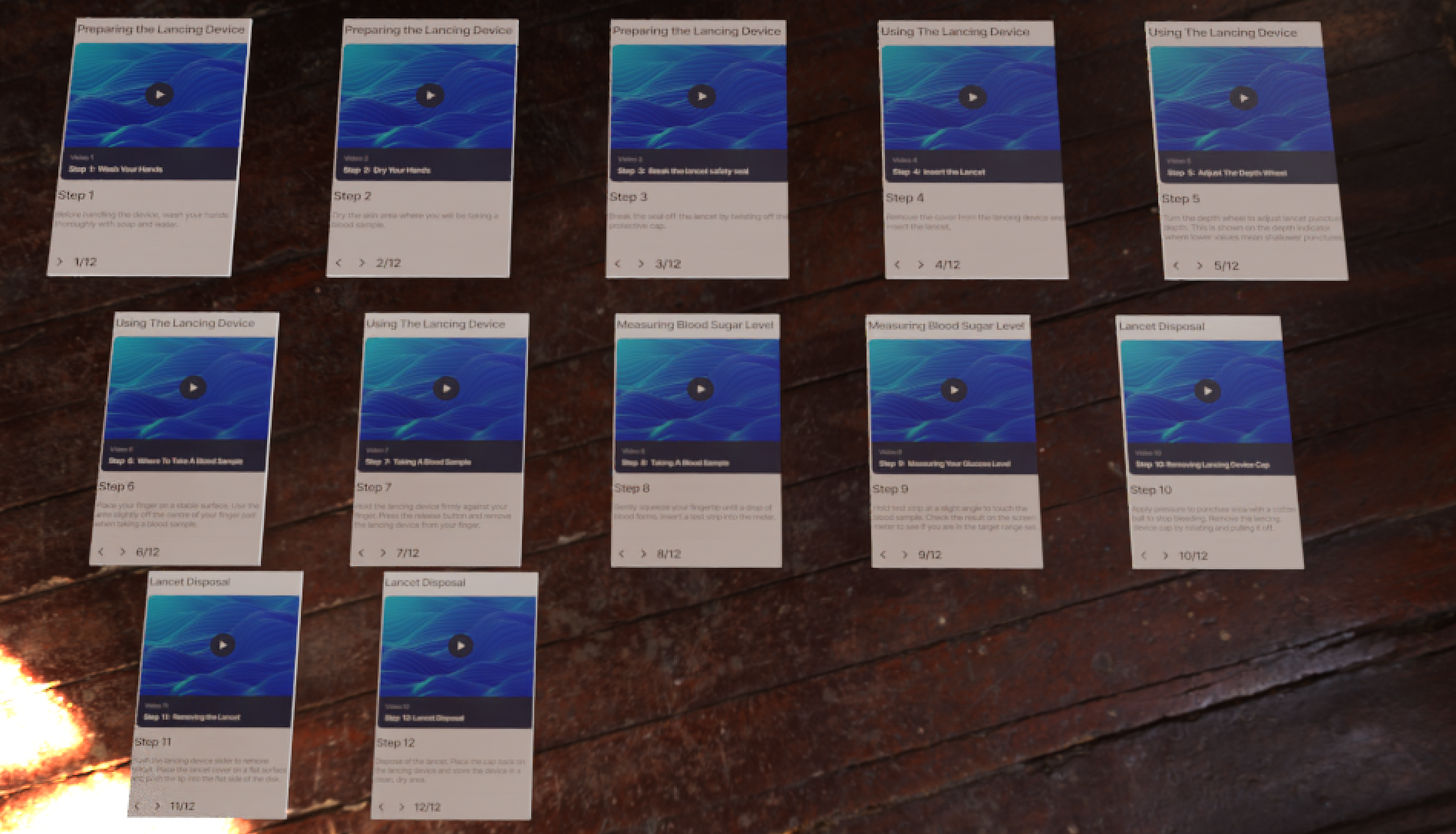 |
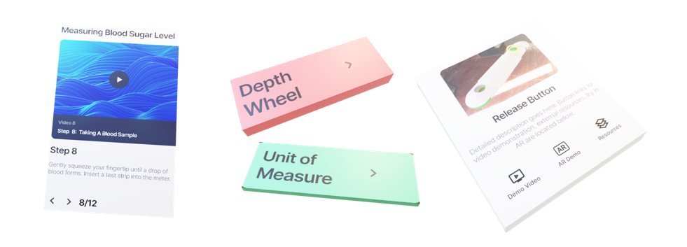
Figure 5: Example set of 3D device parts and user interface items which need to be exported as separate parts.
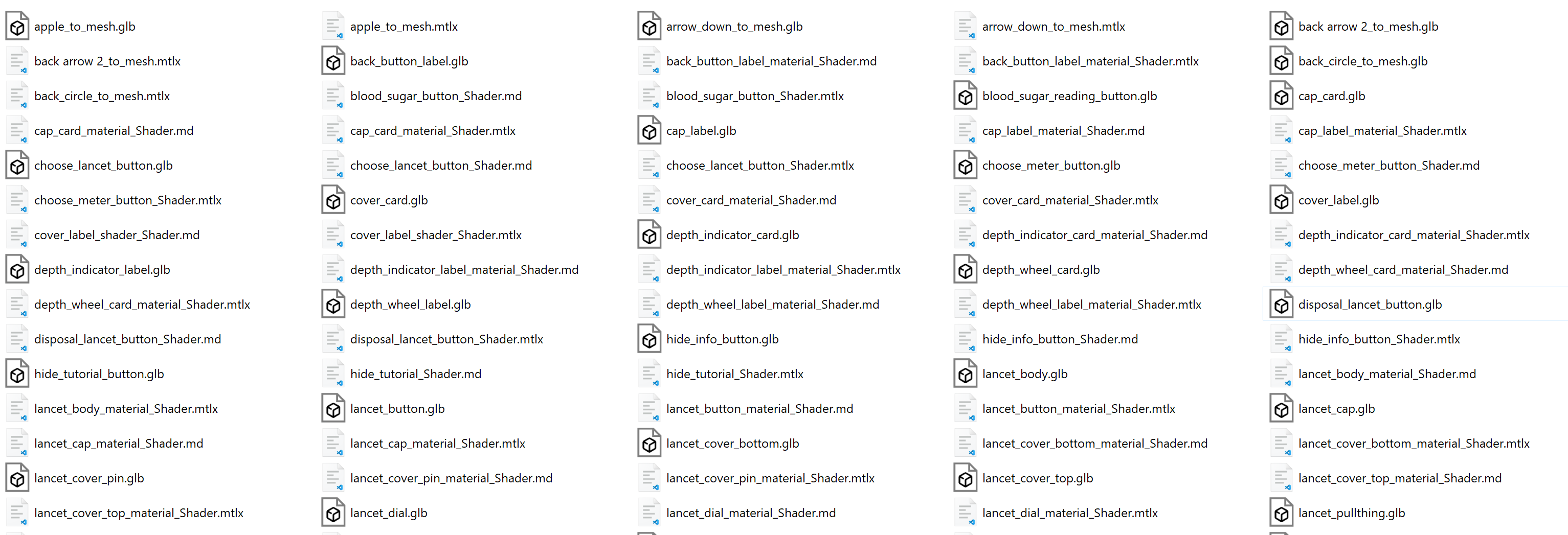
Figure 6 Folder with exported content (material, mesh, shader graph).
Creating 3D Geometry from SVG Files
Icons, logos, and labels are either exported from Figma as SVG files available from public domain websites and asset libraries. Though it is possible to import unedited SVG files directly into Aero, previous experiences have shown that the content is very hard to view and select due to the flat geometry generated.
A script which takes an SVG file and produces a 3D meshes along with MaterialX materials is used for batch conversion of SVG files.
Basic SVG restrictions include:- Backgrounds paths should be clipped (not cover foreground paths) to avoid creating 3D geometry which overlaps. Note that there is no concept of drawing “layers” in 3D as opposed to 2D.
- All paths must be closed.
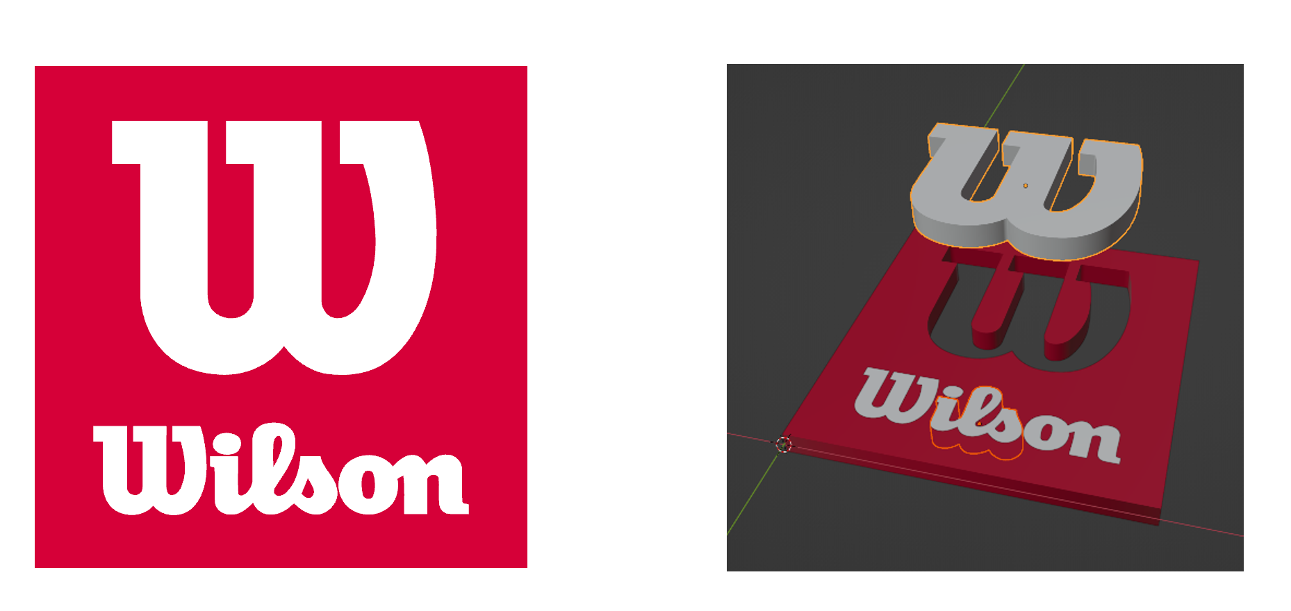
Figure 7: Original SVG (right). Output GLTF loaded into Blender
The main options provided are the extrusion and bevel amount when converting from a 2D curve to a 3D mesh, and whether to export the material with or without shading (flat). The colour of the SVG path is used as the “base” material colour.
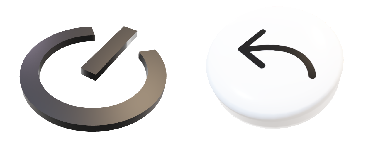
Figure 8: Sample GLTF files (embedded in document). Left SVG has no bevel, while right SVG is bevelled. Each has different extrusion amounts.
Steps To Create a 3D Model From an Image
- Create the image using Figma or Illustrator to draw closed paths. Then export the path as a vector image.
- Alternatively, use an existing png or jpeg image to create the vector image.
- For easier conversion to 3d the image edges should be clearly defined and use single colors. Higher resolution and simple backgrounds also help when converting to 3d.
- Can be imported into Inkscape to ensure paths are closed with no overlapping backgrounds. The basic steps
are:
- Lock the image so the image scales proportionally.
- Use path trace bitmap and fine tune the edges and constraints.
- Drag the trace away from the original image, save the trace as an svg.
- Use the SVG script to turn 2d vectors into 3d models and apply beveling.
Creating 3d Labels From 2d Images
A Python script is used to read in images and create 3d geometry by:
- Importing an image
- Use its dimensions to create a 3D rectangular shape with a user defined height. The default width of the geometry is 1 but can be set as an option.
- Create a material and use the image as the base color input. The material may be unlit or shaded.
The command line options are:
usage: image_to_mesh.py [-h] [--unlit UNLIT] [--width WIDTH] [--height HEIGHT] inputFileName

Reads Image file into Blender to produce a 3d mesh and material. Save meshes to GLTF, material as MaterialX, and Blender file

positional arguments:
  inputFileName    Path containing Image file to convert.

options:
  -h, --help       show this help message and exit
  --unlit UNLIT    Create unlit materials.
  --width WIDTH    Width of mesh to create. Default is 1.0
  --height HEIGHT  Height of mesh to create. Default is 0.1
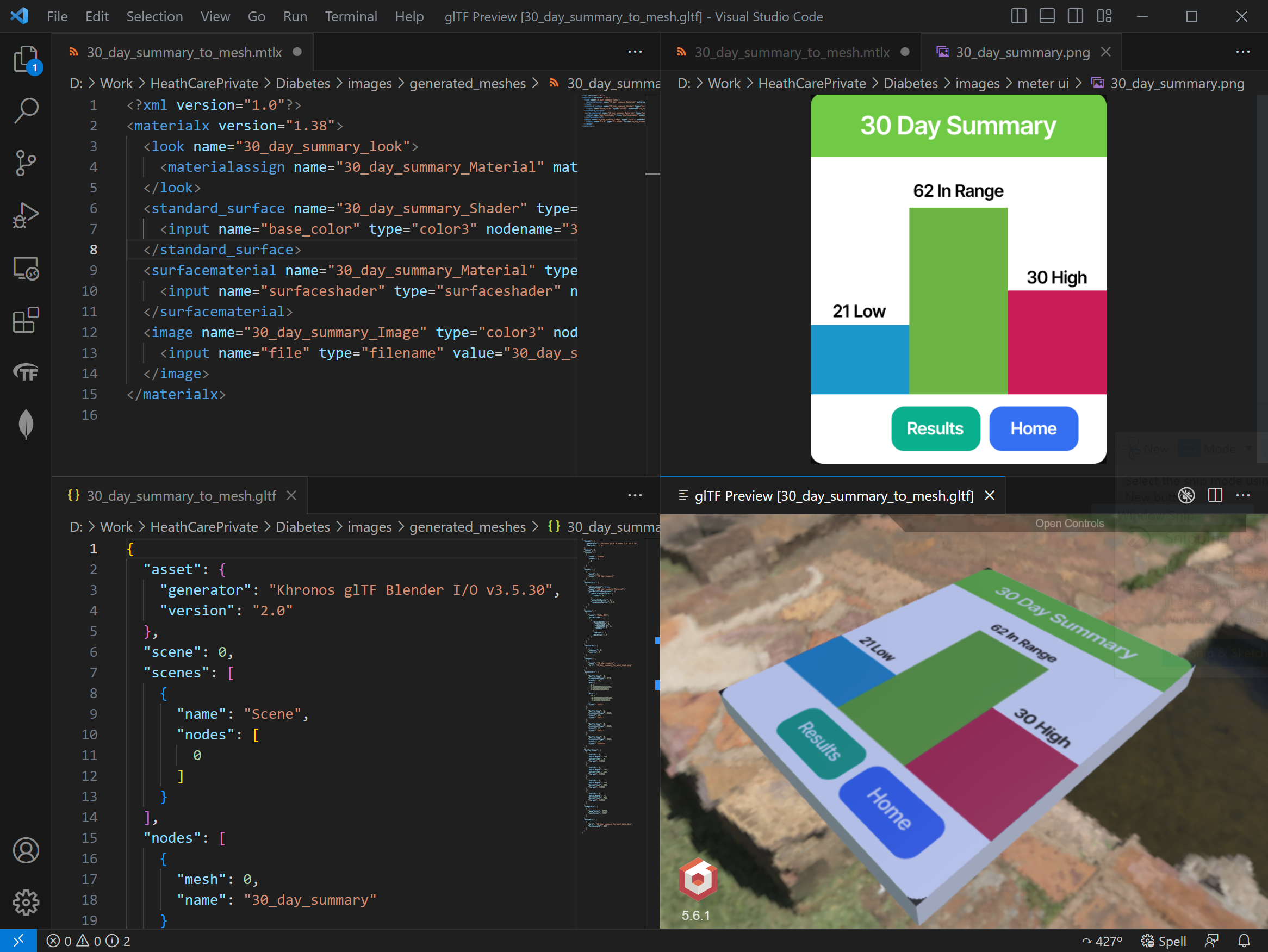
Figure 9 Results of script for a sample image (upper right). MaterialX material (upper left), GLTF geometry (lower left), Geometry rendered (lower right).
Audio Description Voiced audio description was added to provide additional context and instruction when users access the device tutorial or want to learn about a specific part’s purpose for the lancet/meter devices.
ChatGPT was used for text generation of generic instructions for meter and lancet parts. The generated text was then modified to incorporate more specific technical terms and instruction for device usage.
To create audio clips, the instructions were put into the text to speech program Espeak to create separate audio clips for each step. Audio was then exported in WAV format and compressed to ensure that the files could be played in Adobe Aero.
Other methods of audio generation were explored such as the Mozilla TTS library and using Google’s speech synthesis markup language to code audio instructions. The Mozilla TTS library allows you to train an audio model to generate custom audio and more natural sounding speech. This library will be examined in the future for generating longer form audio content. The markup language will also be explored further due to the degree of customization options for the tone, voices, and language of the audio.
  Step 1, take a deep breath.
  Step 2, exhale.
  Step 3, take a deep breath again.
  Step 4, exhale.
Figure 10: Using SSL (Speech Synthesis Markup Language) you can set the duration and strength of speech such as pauses.
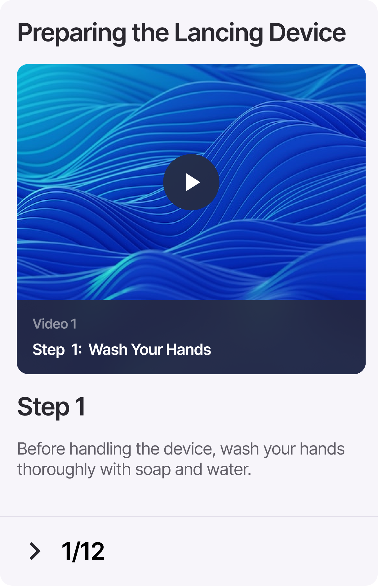
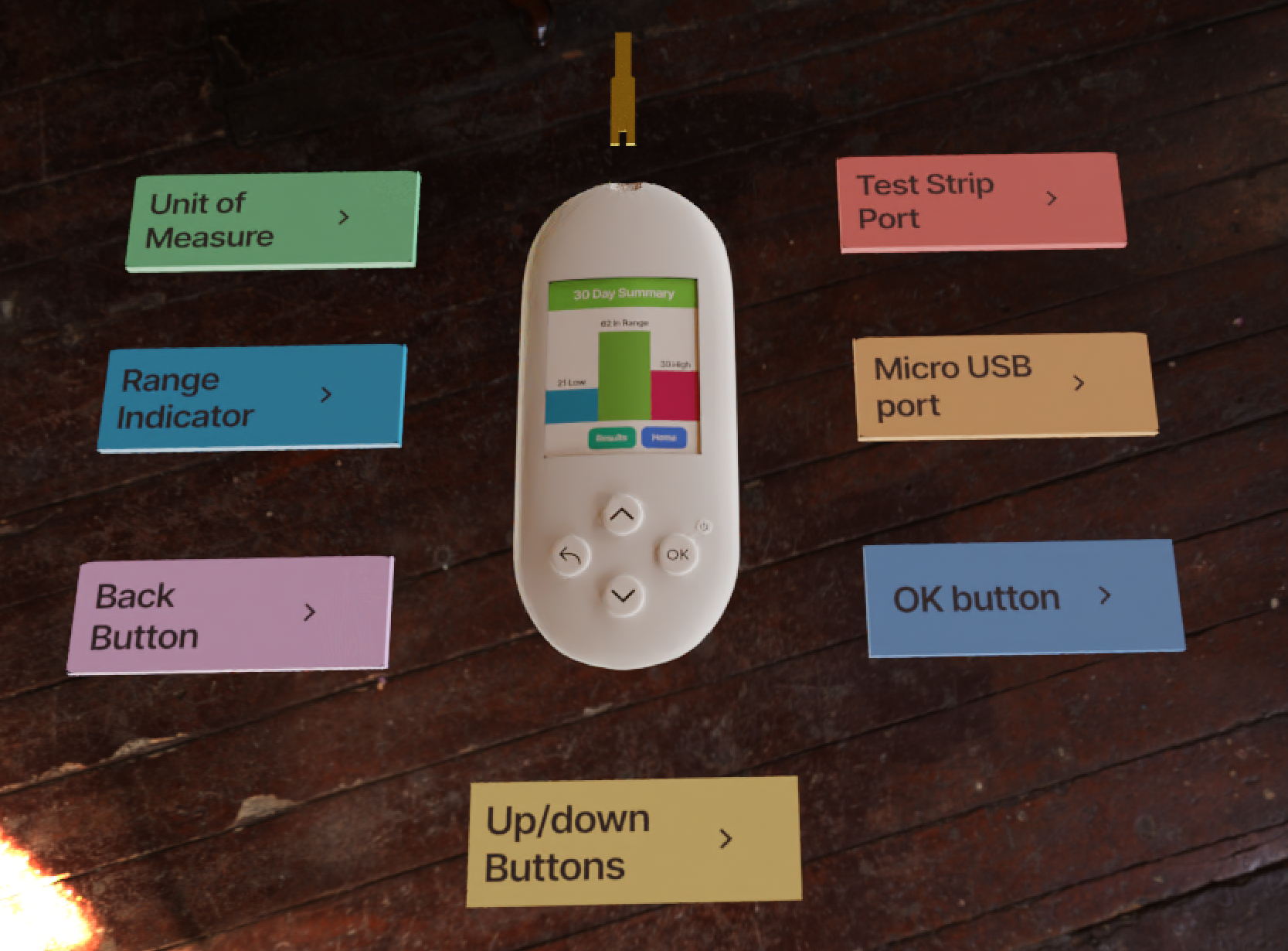
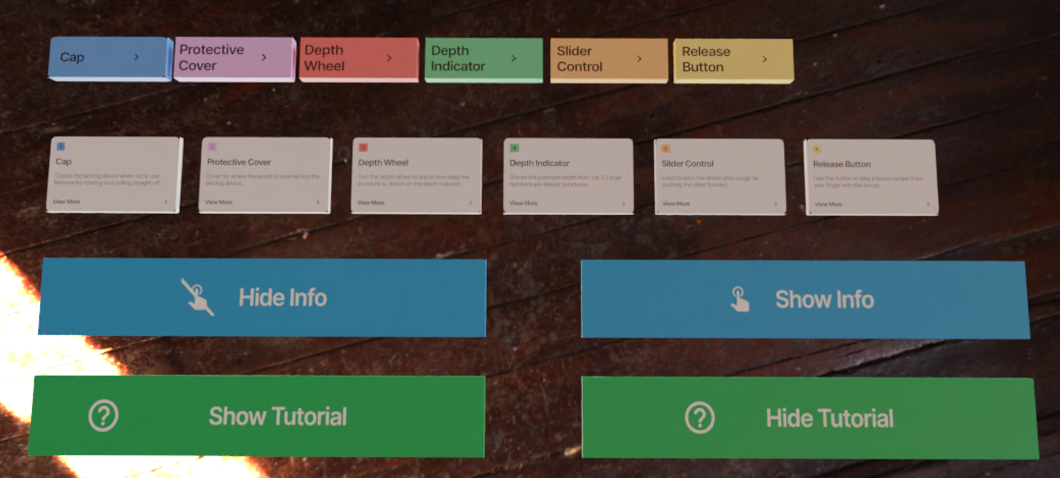
Figure 11. Within AR users can press the play button of the card to playback audio instruction and additional information for device usage.