3D Logo Creation From 2D Illustration
1. Introduction
This article outlines a series of steps followed to convert a 2D logo design (illustration) to a 3D object for rendering or online deployment. As this is a general process the goal here is to provide and outline with some issues and solutions encountered for the mutual benefit of others.
Some interesting points of note for the workflows:
- Image / object compositing which works in 2D may not translate into proper 3D geometry.
- Asset management organization can differ between 2D and 3D.
- Shading, lighting, and texturing while not necessary in 2D is needed for rendering in 3D. Such items should be created as separable reusable assets which can be applied to geometry.
- 3D geometry should be split into logical assets (often based on by appearance (material).
The source logo is one which was produced for a hair salon business as shown below. See the project site for more details
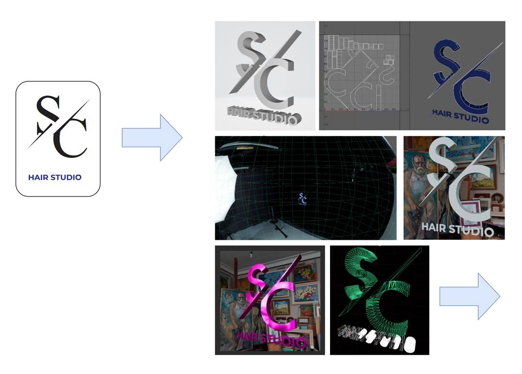
Figure 1 : Initial logo design on left and snapshots taken during the creation process.
Tools
It is assumed for this article that there is access to Adobe Creative Cloud products and some 3D editor. It is possible to use another SVG editor such as Inkscape if appropriate.
The main tools used for this process are:
- Figma : The original icon was created here as part of the design process.
- Adobe Illustrator : The icon was cleaned up here to create an appropriate 2D vector graphic version. (Note: At time of writing, 3D creation is available but appearance setting relies on usage of Adobe Substance Design. This workflow has not been tried but assets appear tied to this ecosystem).
- Autodesk Maya: One option to import vector graphics to produce a 3D version.
- Blender (3.1): Another option to import vector graphics to produce a 3D version. For those who cannot afford the expense of something like Maya. Also used for conversion to standard file format deployments such as for Web (glTF).
- Adobe Photoshop / Camtasia: Either of these were used to create animated images or movies. There are other tools which could be used in lieu of these including free Open Source tools such as ScreenToGif.
- GitHub: Used for maintenance and tracking of the various assets. At each step along the way new revisions were checked into a GitHub repository.
Some useful tools to help with visual checks included:
- Visual Studio Code: There are several syntax and visual preview plug-ins available.
- Visualizer utilities which come native with the platform (e.g., Mac, Microsoft Windows (obj, and glTF).
2. Figma Workflow
The icon shown was created in Figma using a series of font and geometric shapes. As a first attempt all the icon the layers were grouped and then exported as an SVG file. When importing the logo directly to Maya / Blender there were issues related to finding the appropriate vector paths for each part of the logo. This was due to disconnected / disjoint vector paths. As such, proper 3D shapes could not be derived. To address this, the SVG was first processed in Illustrator.
3. Illustrator Workflow
The SVG saved in Figma was imported and then copied onto a blank canvas. The first step was to make sure that all the layers were grouped. After examining the assets, it was found that the icon consisted of several separate disconnected shapes.
To fix this all assets were converted into paths so they could be manipulated. The middle rectangular shape which when applied in 2D as a filled overlay causes issues since it should not actually exist in 3D. It was thus subtracted from the “S” and the “C” sides using: Subtract from Shape Area. This cut out the area of the component from the underlying geometry resulting in two distinct closed vector paths (for the “S” and “C” respectively).
The fill color for each path is set to be mono-chromatic as the colors are not used on import to create the 3D materials. The color palette was also exported separately for usage when creating 3D materials.
 |
 |
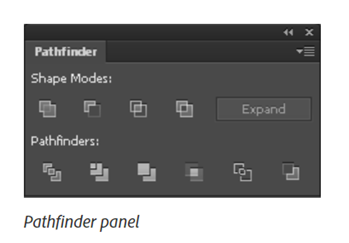 |
Figure 2: The rectangle in the middle of the “S” and “C” was removed using Subtract from Shape Area in the Pathfinder tool (on right). The icon was then grouped for export.
Export from Illustrator
To allow for each object to be placed independently and to have different 3D materials, the “S” and “C” was exported as one SVG file and the “Hair Studio” part was exported as a second SVG file.

| 
|
Figure 3: The two parts of the logo.
4. Maya Workflow
From inside Maya and “SVG” object was created for each SVG file, and the files were imported.
4.1 Geometry Workflow
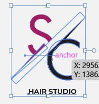
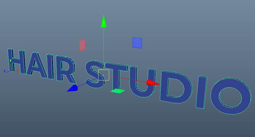
The first thing to note is location of the transform pivot as by default it is in the lower left front corner of the object bounds. This is fine for 2D text on a plane but is non-intuitive for 3D transformation the icon (e.g., if you want to create a turntable animation of the icon. To address this the pivot was centered within the 3D bounding box.
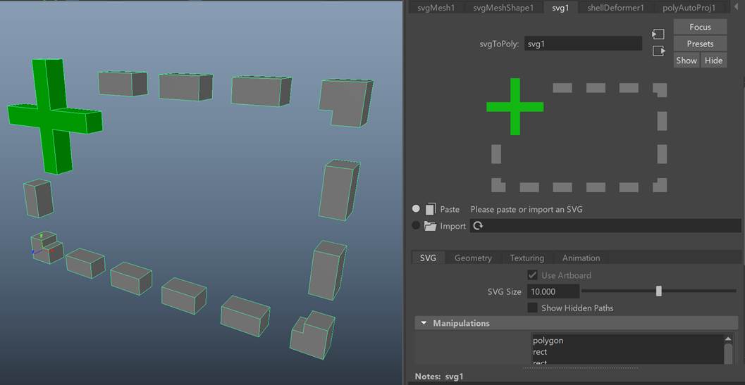
Figure 4: Pivot default position is in the bottom left corner.
It may also be the case that the scale of the geometry needs to be modified. Though possible to scale within the SVG import node, it is more flexible to leave the geometry as unit size and scale using its parent transform. As the pivot was previously centered the scaling will be about the local origin of the object.
| 
|
Figure 5: After the pivot centered is centered, using the Modify->Center Pivot operation. The object has also been scaled about this new pivot as desired.
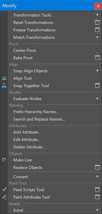
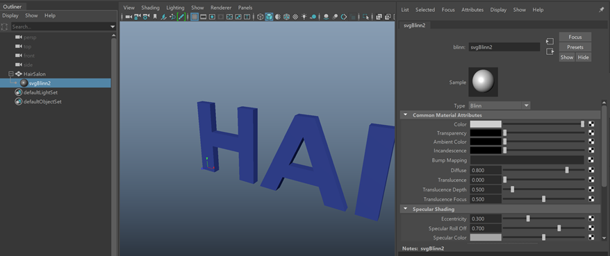
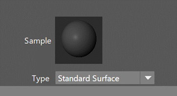
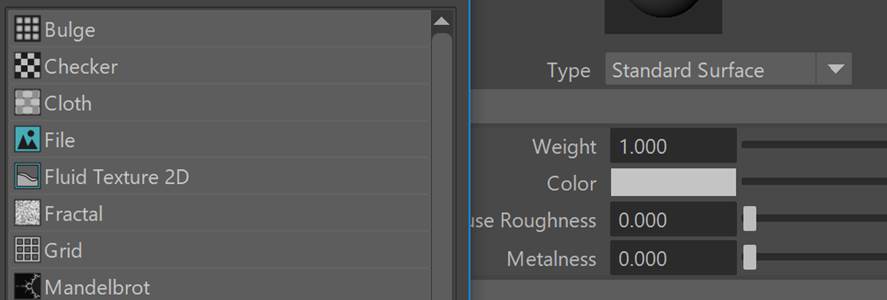
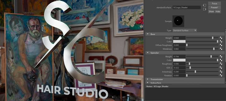
The next modification was to the material type of the object. Originally Maya set the default material to Blinn which is not portable outside of Maya. To conform more with current material standards this was changed into a “Standard Surface” material. As part of the geometry setup step, it is also useful to set the material properties so it’s easier to see highlights and evaluate smoothness.
|
|
Figure 6: Change from non-standard “Blinn material” to Standard Surface.
Note: A generally good practice is to name both the object as well as the materials so that they can be more easily navigated to and managed. It is particularly useful to have good logical names when exporting to different 3D formats.
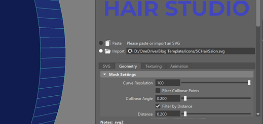
With the basic geometry set up and a proper material to visualize we examined the actual geometry created. As a first step the curvature or smoothness was examined. When converting from an SVG path to 3D geometry it is tessellated. The more subdivisions used to sample for tessellation the better the match to the curvature of the original curves.
The default setting the subdivisions for curved surfaces is generally too low and thus the shapes appear rough. To fix this the curvature resolution was increased to make it smoother. Note that the higher the curve resolution the greater the geometry and hence the larger the resource size. It is up to the user to determine a good balance.
|
|
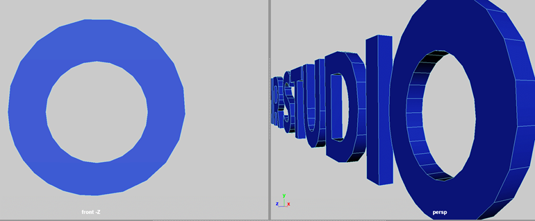
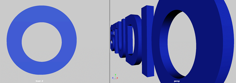
Figure 7: Default curvature vs. curve resolution set to maximum.
As a final step for initial arrangement, the objects are oriented from within the orthographic view by translating and scaling the objects.
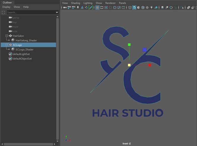
Figure 8: Desired placement for logo.
4.2 Shading / Material Workflow
4.2.1 Lighting Workflow
To visualize materials some lighting is required. For this a “sky dome” environment object was created. Any appropriate input image can be used. Here the following equirectangular (latitude-longitude) image from HDR Haven (which has a permissive license) was used: https://polyhaven.com/a/studio_small_03 .
It is also possible to produce your own 360 environments using a regular camera and stitching software, but this is beyond the scope of this article.
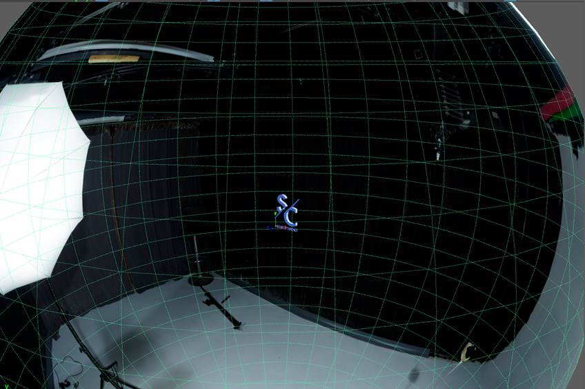
Figure 9: Snapshot of logo with environment preview.
4.2.2 Texturing Workflow
Texture coordinates (UVs) allow for images to be mapped to the surface of the objects in the logo. Missing coordinates means nothing will be mapped, and poorly defined UVs may not end up mapping to the correct parts of the image or cause visual discontinuities.
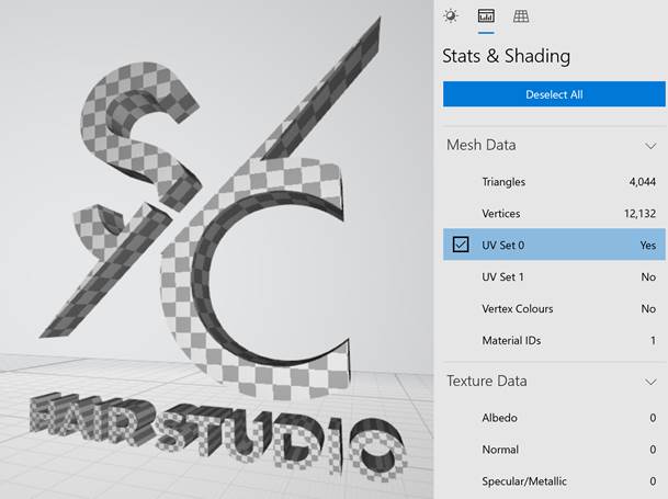
One way to diagnose this is to examine the mapping in the UV editor. It was found that the default UV projection used for imported SVGs did not produce a mapping for all texture coordinates as shown below:
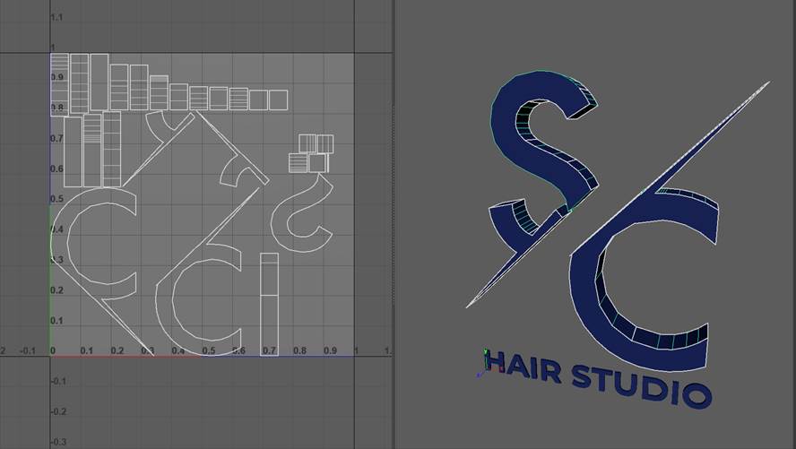
Figure 10: Various pieces of geometry created for the SVG have no texture coordinates. E.g., Part of the “S” is mapped.
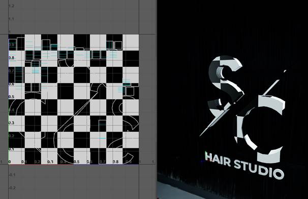
Another more intuitive way to diagnose these issues is to create a checker (or any regular pattern) texture and apply as the color for the materials. The checker can either be applied to the current shaders or applied to a new “diagnostic” shader for visualizing in 3D. Whatever approach which is most convenient may be used.
An easy way to create UVs is to apply a new UV projection which matches the shape of the object. For example, a cup shape could use a cylindrical projection. In this case a box projection was used to map texture coordinates for each part of the logo.
|
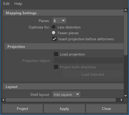
|
With textures correctly mapped any temporary shader used can be removed / unassigned. Different IBLs were experimented with for rendering along with different input parameter values or textures set on the shaders to achieve the desired effect.
|
|
Figure 11: Experimenting to create a metallic look for the logo.
4.2.3 Rendered Output
If output renders are desired, then camera position and rendered image resolution can be modified. While in the 3D viewport make sure to turn on gate masks and resolution masks to ensure that the logo objects are not clipped when rendering. Shown below are some sample renders using Arnold.
4.3 Export / Validation Workflow
Some common export formats are: OBJ, GLTF, and USD. When export exporting the format or the reader for the format may not handle all geometry. For example, polygons which are greater than 3 or 4 sides may not work. To be safe the geometry can be triangulated before export. Note that it might be worth to duplicate the original and only tesselate the copy.
Depending on the format and package used again not all materials may export properly (or at all). If so, then materials may need to be (re)done after export.
Once the objects have been exported you can preview it using a variety of viewers such as those found in editors like Visual Studio Code or the default “3D Viewer” on Windows platforms, or even browsers.
|
|
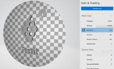
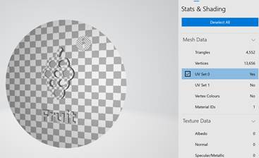
Figure 12: Built in Windows viewer showing texture coordinates. On right, another 3D logo showing missing UVs (top) and UVs after being fixed (bottom).
4.4 Animation Workflow: Basic Turntable Setup
To provide a way to examine the logo from a variety of angles, a looped animation was created to simulate the object rotating on a turntable. The first step was to determine which way was “up” (up-axis) and then set keyframes on the logo at frame 0 and frame 360 to match 0-to-360-degree rotations along that axis.
In Maya the up-axis is Y. A “front” view was used to show how the object would rotate head-on at 0 degrees. Keyframes were placed at various points between 0 to 360 such as at 90, 180, and 270.
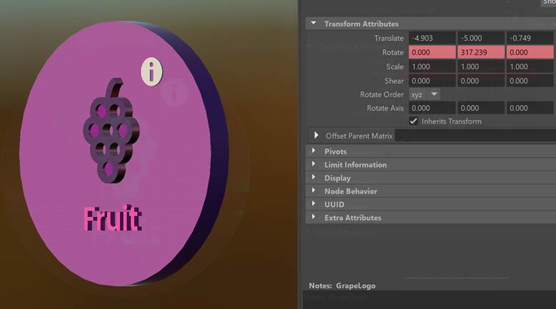
Figure 13: Rotation on logo at a given keyframe.
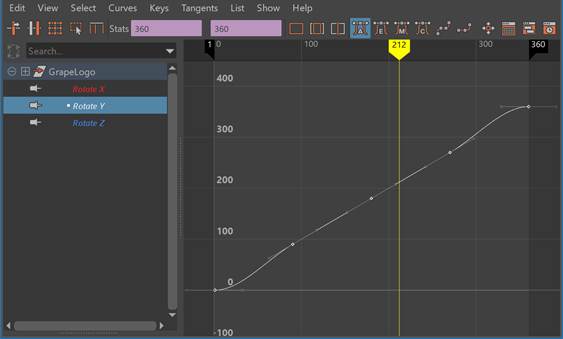
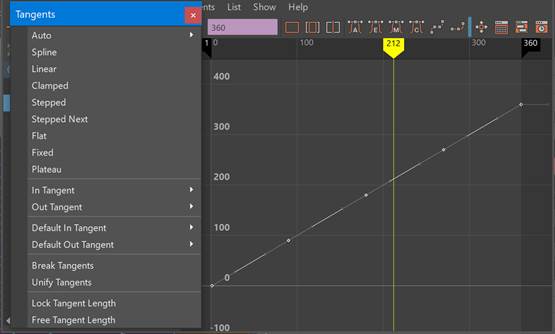
Upon playing back the animation it was noted that the object wasn’t rotating at a fixed speed. To fix this the animation curve needed to be “linearized” so the rate of rotate was even.
| 
|
Figure 14: Pre and post linearize tangents for rotation in Y curve.
The rendering process can be very long and for preview not worth the wait. Instead a quick way to record is to use the viewport to capture an animated gif. In this case ScreenToGif was used save on time for this demonstration.
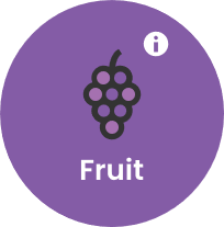
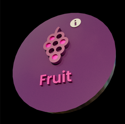
Shown below is another original “Grapes Icon” SVG (left) and the 3d version (right):
| 
|
Figure 15: Low quality animation capture using ScreenToGif.
5. Blender Workflow
The following workflow uses Blender version 3.0.1.
5.1 Geometry Workflow
SVG import in Blender takes a different approach for the geometry than Maya, where no 3D effects are applied on import and the imported object type remains a set of curves.
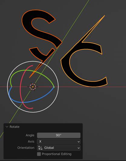
This includes any extrusions or additional scaling. For the latter case it may appear that the import did not work since the initial size is very small. Thus, the first step is to transform by scaling and rotating the objects so that they are large enough and rotated to no lie on the ground plane.
| 
|
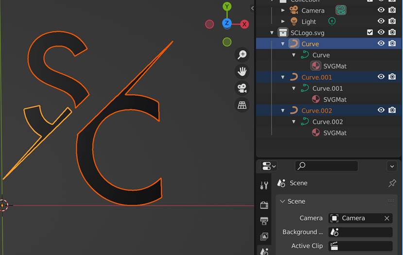
Figure 16: Rotation so that SVG is not lying flat. Imported SVG remains as curves on import. Note that a separate material per curve is created on import, which differs from Maya.
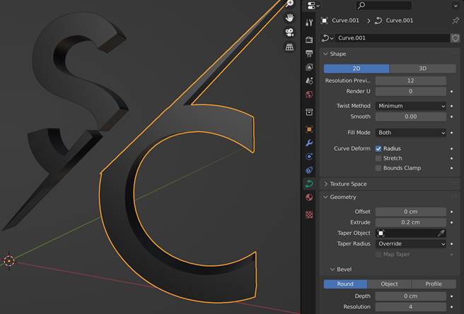
Next the various shape parameters can be adjusted.
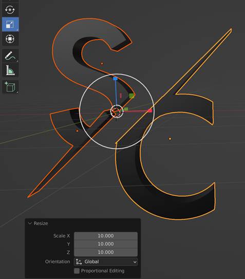
Here, the curves can be extruded to create a 3D object and then scaled to the desired size. As previously stated, it is imported to center the pivot (Object->Set Origin->Center of Volume), before performing any transformations otherwise the objects will scale based on the default pivot (lower left origin).
| 
|
Figure 17: Shape adjustment panel (left) showing appearance options including setting the amount to extrude. Scaling about pivot at center of objects (right)
After setting the desired appearance and placement, the curves can be converted to be meshes for material assignment or exported for external review. Note that glTF format export is supported natively (unlike in Maya), which makes for faster review iterations for shading / materials.
5.2 Shading / Material Workflow
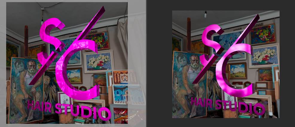
For review within Blender, it is recommended to set the renderer to be Cycles or some other photorealistic renderer. After this is set up, values can be changed to evaluate the shading on the 3D objects. To perform proper shading evaluation shader node usage this should be enabled, and material assignments should use Principled BSDF materials.
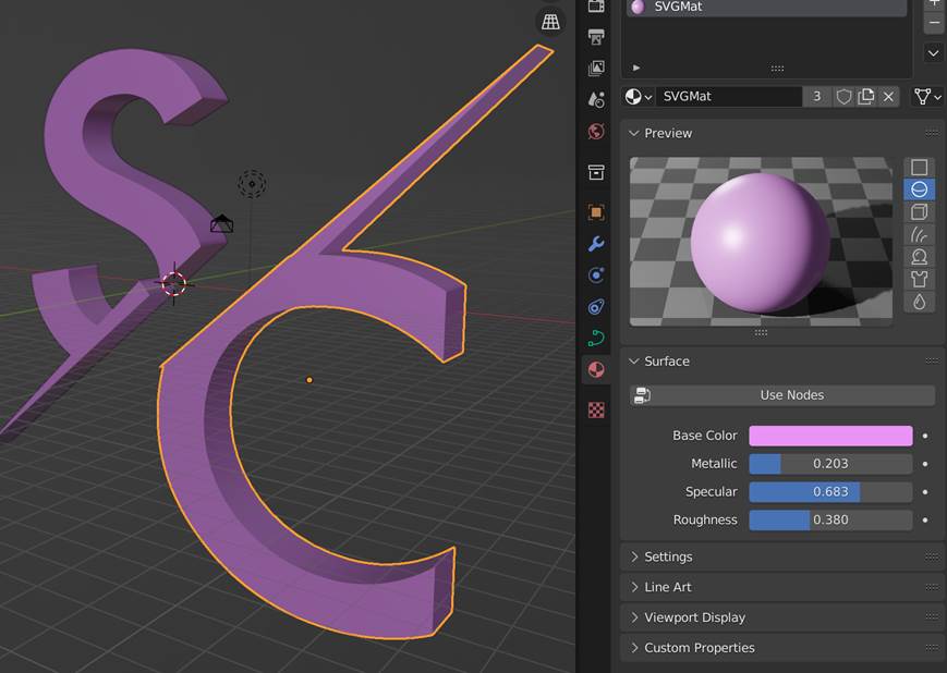
Figure 18: Mesh with PBR material. Adjustments can be previewed in viewport or the Preview window. Cycles has been set to be the renderer and the material set to be “pink”.
With shading evaluation set up, more curve adjustment can be performed. This can optionally include beveling the edges of the logo. Note that this must be done on the original curves and as such mesh conversion should not be performed yet, or if performed to a produce a secondary instance.
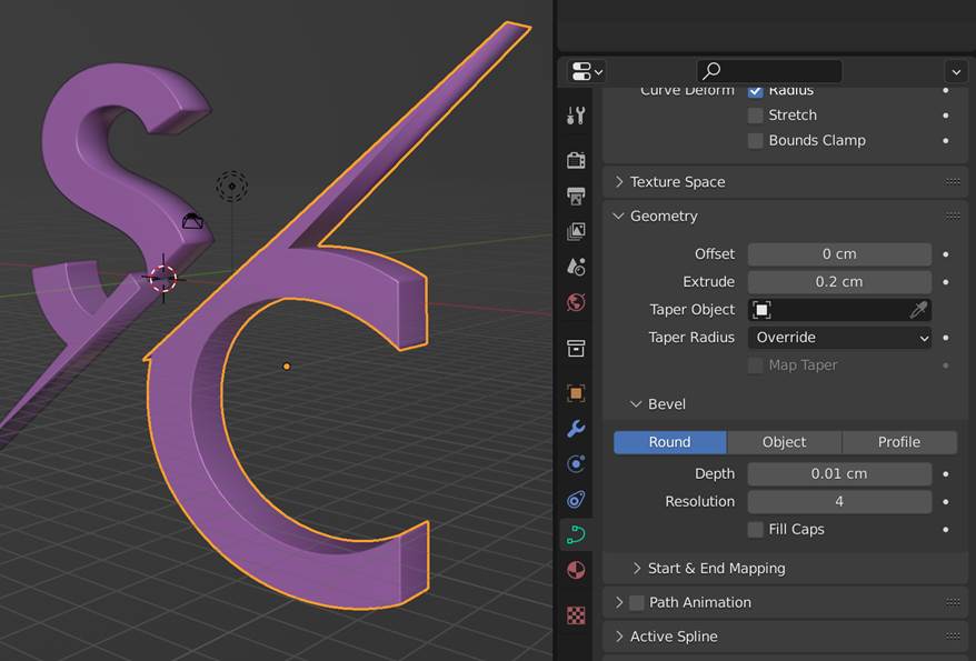
Figure 19: Optional bevelling to enhance the appearance of the logo.
Blender has a set of preset interface arrangements which focus on different workflows. To adjust shading, “Shading” mode should be chosen which sets up the UI for shading / rendering preview and shading graph manipulation as shown below.
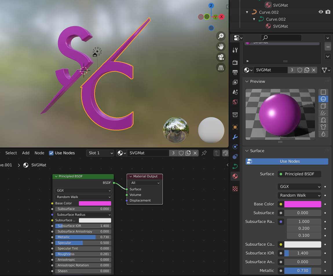
Cycles is the default renderer used, but other renderers can be chosen (such as Eevee) for better quality feedback.
5.3 Lighting
From within the shading graph editor, environment lighting can be set up. First the shading mode needs to be set to “World” to set up shaders which affect the entire scene (or world).
An environment texture node can be added, and a suitable IBL input image chosen. Connecting the node to the world output enables the environment. Disconnect the “Background node” (which provides a constant color environment) as needed.
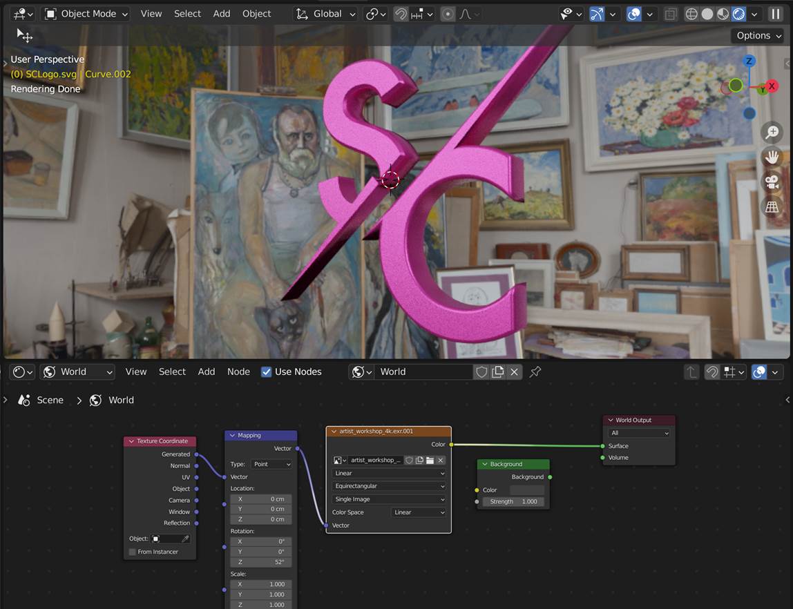
Figure 20: Environment setup with input IBL node and placement. Preview has been set to use the current renderer set (Eevee in this case)
There are a number of sites to obtain free to use HDRs (CC1 licensing) from. For this scene and example from https://polyhaven.com/hdris was used.
Note that if you wish to have control over the placement of the environment a “mapping” and “texture coordinate node can be added. For example, you may wish to adjust the rotation of the environment. Switching the Shading panel to show rendered output allows for interactively preview rendering to occur.
5.4 Texturing Workflow
To fix the texture coordinates, we again take a similar approach of adding a checker texture as input color to preview.
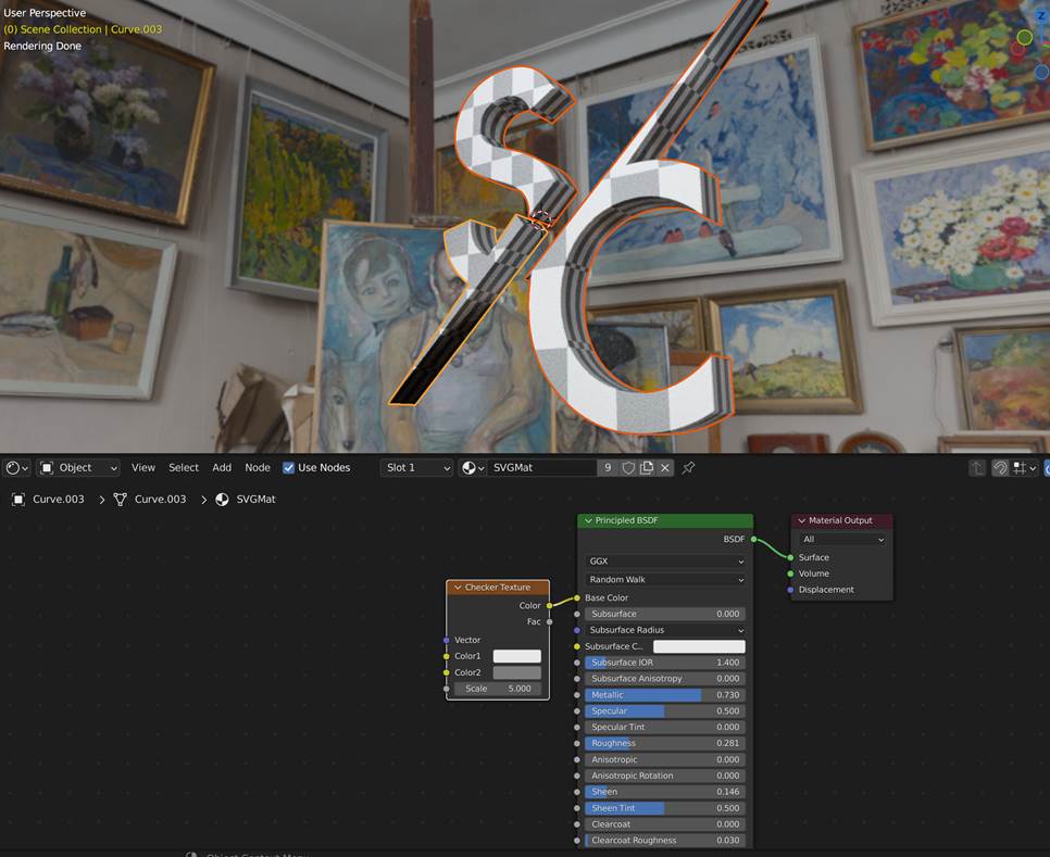
Figure 21: Checker texture assigned to base color for preview (bottom). Preview of checker (top). Shown is result after box projections have been applied.
To adjust / fix the coordinates, “Edit mode” can be entered for each object and a suitable UV projection can be performed. A box projection works well in this case.
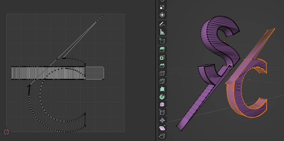
Figure 22: Texture coordinates shown in the UV editor (left) and in 3D (right).
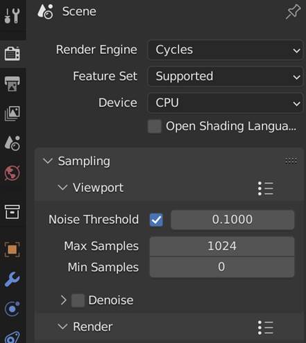
5.5 Rendered Output
The output settings can be specified using the "Output Properties" panel and rendered out. Rendering is progressive (refines over time), but an output image can be saved at any time while it refines.
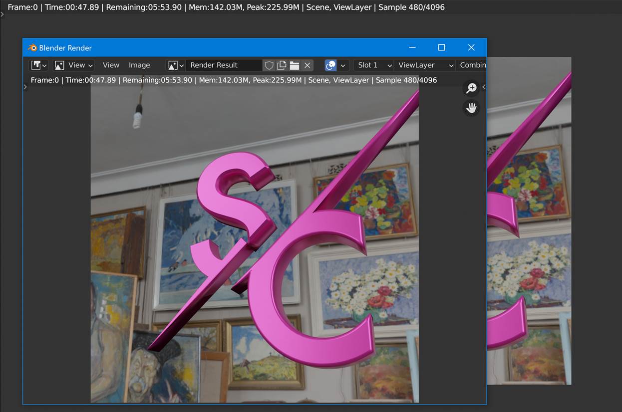
Figure 23: View of rendering in progress showing progress (480 samples out of total 4096) with estimated remaining time shown. For output settings a 1K square image was rendered.
5.6 Animation Workflow: Basic Turntable Setup
If not the case, ensure that all objects for the logo to rotate are parented under a single transform. One way to do this is to create an “Empty” object.
This top-level object can have animation applied to it by keying the Z-axis’s rotation angle from 0 to 360 degrees. The frame range can be set from 0 to 360 to ensure that the animation will repeat properly.
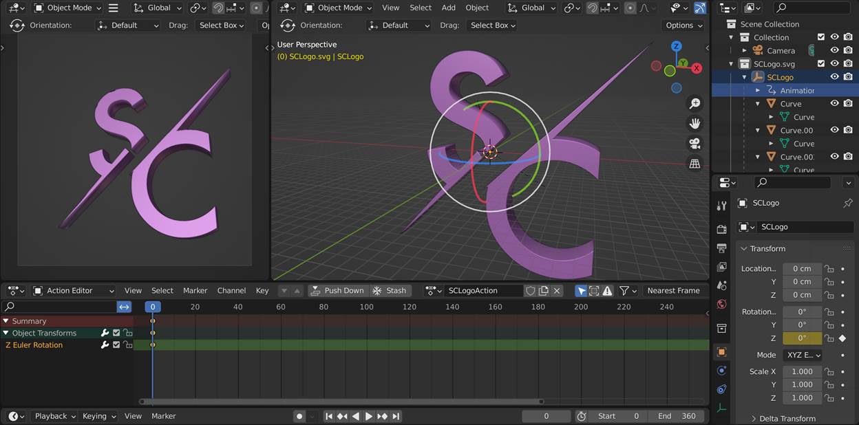
Figure 24: The empty parent SCLogo’s transform has been keyframe animation such that the Z-axis goes from 0 at frame 0 to 360 degrees at frame 360.
Again, a check should be made that the interpolation is linear for the animation curve to ensure constant speed. This can be done in the “Graph Editor” by selecting the curve and setting the Key->Interpolation to be linear.
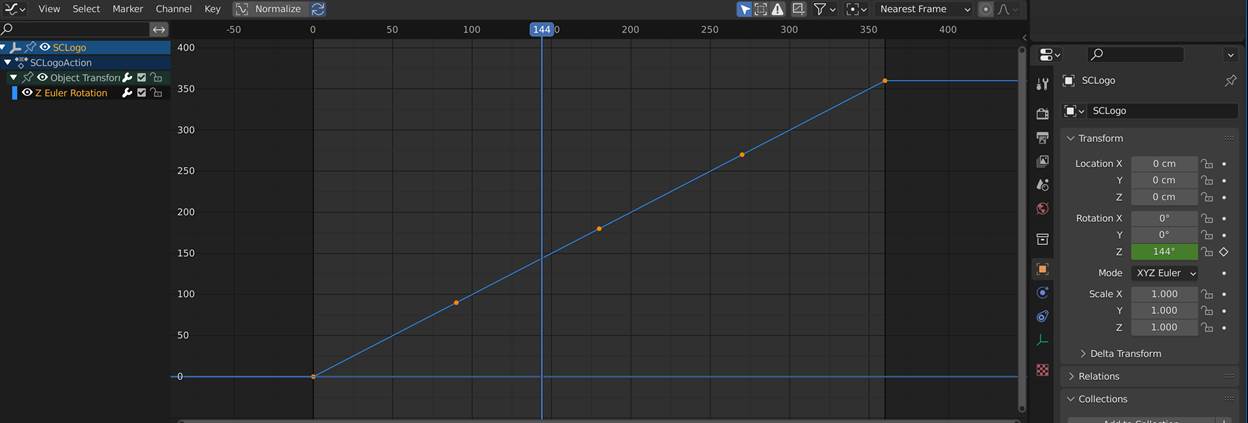
Figure 25: Curve of rotation in Z of logo after being linearized in the Graph Editor.
Figure 26: Animated output after exporting to glTF. Native Windows preview utility was used.